There are three basic methods of connecting a lead screw to a hollow shaft motor in order to create an external linear actuator system. Here are some of the advantages, disadvantages, and effects on performance associated with each of these methods.
There are several styles of motion-control couplers that can be used to transfer the rotary motion of the motor into an attached lead screw. These couplers are installed on the stud shaft that extends from the motor and are also connected to a machined journal at one end of the screw. This type of configuration requires more physical space to accommodate the length of the coupler and any associated attachment housing. Due to the increased number of components, tolerance stack ups, and the complexity of assembly, couplers are more susceptible to misalignment and therefore exhibit difficulty at holding each piece on centerline. The result of this misalignment can be a cam type effect on the coupler and the screw, transferring additional forces into the motor or screw and shortening the life of the system.
Traditional Motor and Screw Setup
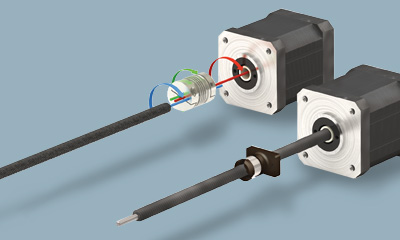
Integrated Hybrid Linear Actuator Setup
Another common method used for the assembly of actuators with external lead screw motors is the insertion of a machined journal at one end of the screw into a tapered bore within the motor. The screw can then be mechanically secured into place from the back side with a bolt. This assembly method is most often chosen when a large amount of maintenance is anticipated. Using the threaded mechanical method to hold the screw in place provides a quick method for disassembly and reassembly. The drawback is the difficulty in establishing and holding alignment. The result of any runout and misalignment is a “snow cone” effect that amplifies any inaccuracy over the length of the screw. It is especially evident with applications requiring longer screw. This “snow cone” or wobble effect in the screw will create forces that are transferred to other components within the system. The results are wear on the nut as well as additional load on the motor, shortening the system life and resulting in the need for further maintenance or possible premature failure.
For our external lead screw motor actuators, PBC Linear uses a direct connection between the screw and the motor. The machined journal at one end of the screw is manufactured to a tight tolerance and slip fit, with little clearance, into to a hollow shaft within the motor. This method ensures the maximum engagement between the fit of the screw and the motor, resulting in the highest accuracy alignment possible. The screw is then permanently fixed at the back of the motor using an industrial adhesive.
The PBC Linear method, with its close-fitting tolerances, maximum screw and motor engagement, and permanent bond, minimize the need for straightening and provide the highest level of accuracy, the least amount of screw runout, and the elimination of the “snow cone” effect.
To find more in-depth information on lead screw assemblies, please read the Design World article: Linear Motion Systems: Only as Strong as Weakest Link, or read our blog Linear Motion Design Elements of Lead Screws.